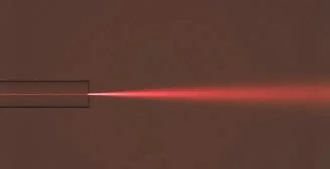
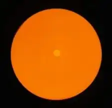
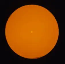
The two photos below show free-space beams output from multimode and single-mode fibers respectively.
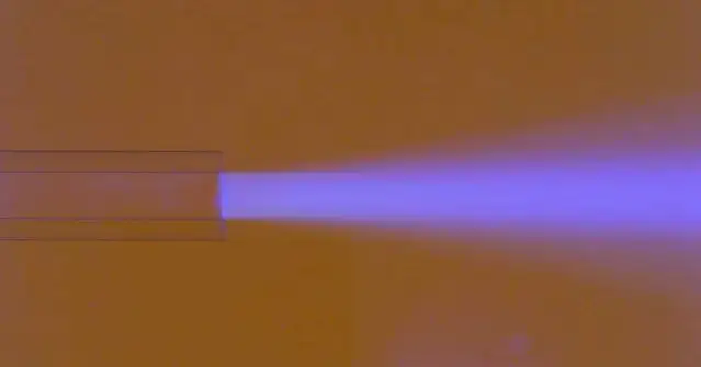
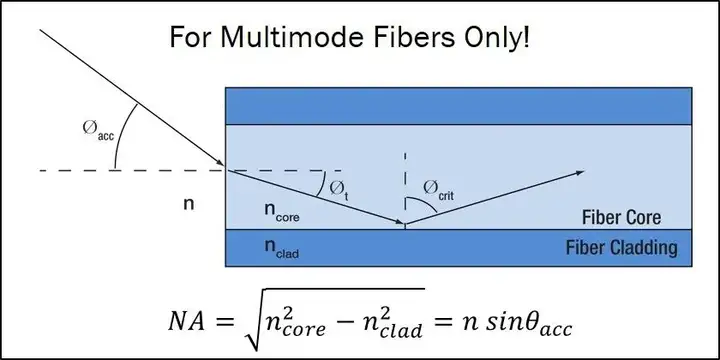
The output beam properties of multimode fiber can be simulated by geometric optics: the output angle/acceptance angle is related to the incident angle at the core-cladding interface when total internal reflection occurs, and is also related to the refractive index difference (NA) between the core and the cladding. .
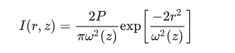
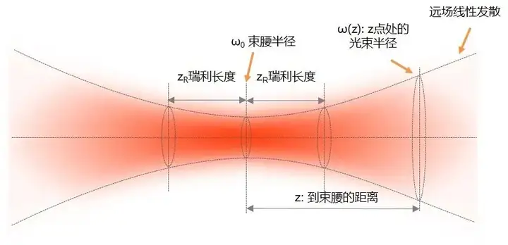
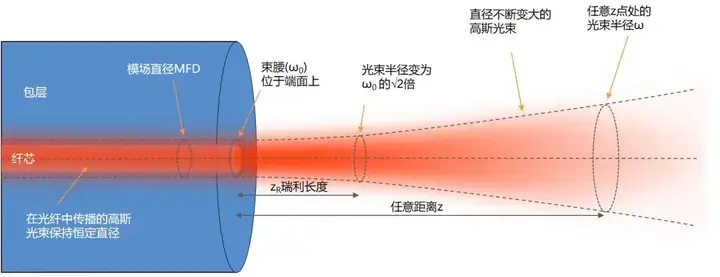
Single-mode fiber output needs to be simulated by Gaussian beam. The intensity of a Gaussian beam is represented by a Gaussian function. It has the same intensity profile at any z point on the optical axis, but the beam diameter is constantly changing, and the smallest beam diameter is called the beam waist. The smaller the beam waist, the larger the beam divergence angle. When other conditions are the same, the shorter the wavelength, the larger the divergence angle.
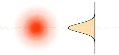
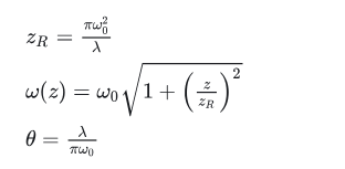
It may be easier to judge the properties of a Gaussian beam through formulas. Gaussian beam radius (ω) is expressed using the 1/e² radius. The Rayleigh length is the propagation length from the beam waist when the beam diameter becomes √2 times or the cross-sectional area becomes 2 times. A divergent beam has a shorter Rayleigh length and a collimated beam has a longer Rayleigh length. The divergence speed of the beam has a nonlinear relationship with the propagation distance in the Rayleigh range, but becomes linear after entering the far field, and is only related to the wavelength and beam waist.
Single-mode optical fiber outputs a free-space Gaussian beam whose beam waist diameter is equal to the mode field diameter of the optical fiber. In the above formula, if half the mode field diameter (MFD) is used to replace the beam waist radius of the free space beam, the Rayleigh length of the fiber output beam, the beam radius at any position, and the far-field divergence angle can be calculated.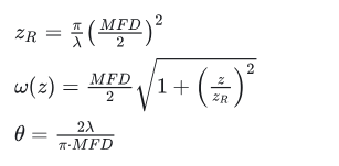
Although the far-field divergence angle of single-mode fiber output is calculated only by wavelength and beam waist radius, the indirect effect of NA is also worth noting. NA may be defined differently. For example, Thorlabs defines NA based on the refractive index difference between the core and cladding, while Corning states in the specification sheet that the NA of SMF-28 fiber is measured at the 1% power level of a one-dimensional far-field scan at 1310 nm.
Because the same cutoff wavelength can be achieved through different combinations of NA and core diameter, and the smaller the core, the smaller the mode field diameter, but the larger the divergence angle, so NA will also indirectly affect the divergence angle of the single-mode fiber output . For details, please see the comparison of design parameters between standard communication optical fiber and a high-NA spliced optical fiber.
Core diameter 8.2 µm, 0.12 NA, cut-off wavelength 1285 nm, MFD 10.4 µm @ 1550nm, far-field divergence angle: 5.44°
Core diameter 2.81 µm, 0.35 NA, cut-off wavelength 1284 nm, MFD 3.57 µm @ 1550nm, far-field divergence angle: 15.84°
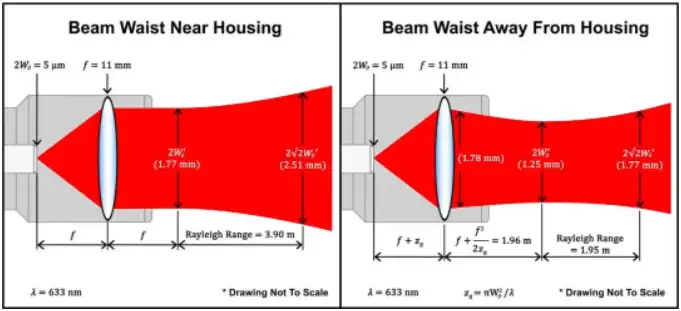
Collimation is equivalent to using a lens to convert a small beam waist and high divergence beam into a large beam waist and low divergence beam. We can use the thin lens formula for Gaussian beams as a reference. If the focal length is much larger than the Rayleigh length, as is the case with highly divergent beams output from optical fibers, then the additional items in the box can be omitted. The collimated beam radius output by the lens can be calculated from the mode field diameter, focal length and wavelength.
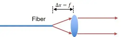
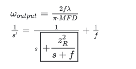
For fiber collimator designs, if the lens is placed slightly larger than the focal length, the output beam waist will be pushed further away from the collimator, achieving a suitable working distance.
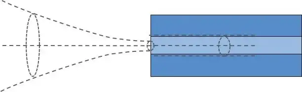
Coupling is the inverse process of collimation, but it is also a much more complex process. Coupling efficiency is the ratio of the power coupled into the fiber to the incident beam power.
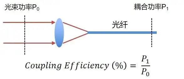
In order to achieve high coupling efficiency, the incident beam must meet several conditions:
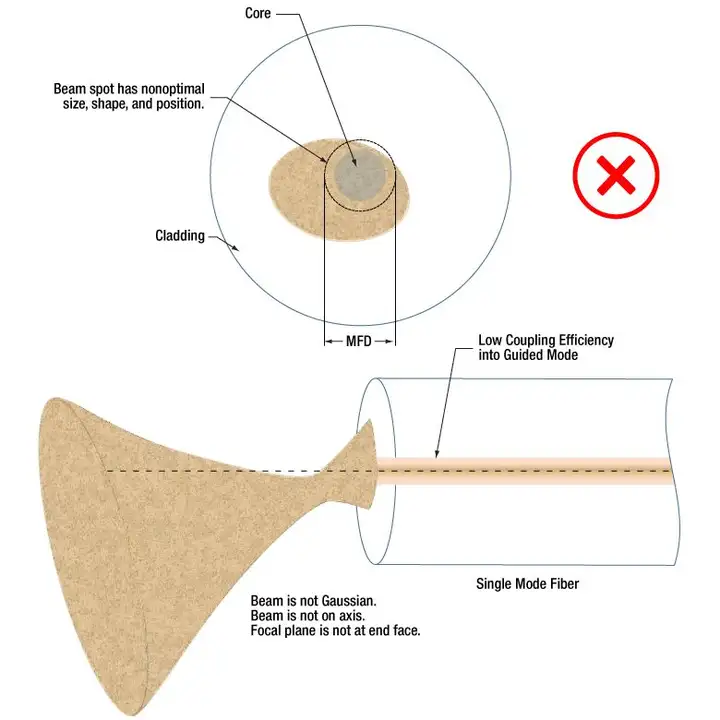
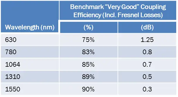
In a laboratory environment, a single-mode fiber coupling efficiency of more than 85% is considered to be a very high level. The following table shows the efficiency of certain Thorlabs fiber coupling devices at different wavelengths. The longer the wavelength, the higher the coupling efficiency. This is because the shorter the wavelength, the smaller the mode field diameter, the higher the positioning accuracy requirements, the more difficult it is to meet the optimal coupling conditions, and the scattering at short wavelengths is also greater. In addition, the coupling efficiency of non-Gaussian beams is very low.

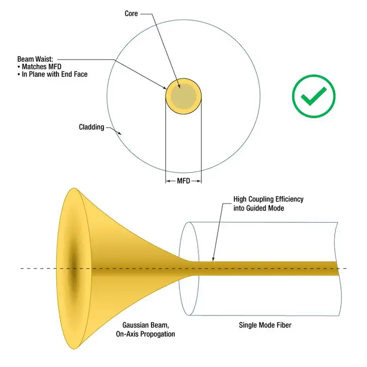
Any deviation from optimal coupling conditions will result in reduced coupling efficiency. The effects of beam waist and mode field diameter mismatch, lateral deviation, and angular deviation on coupling efficiency can all be estimated through theoretical formulas.
For the case where the beam waist and mode field diameter do not match, if the beam waist is larger than the mode field diameter, the peripheral beam cannot be coupled, and the efficiency is therefore reduced. This is well understood, but it is a bit counterintuitive that the beam waist is smaller than the mode field diameter and the efficiency will also be reduced. . Ultimately, this is because the light spot does not meet the mode requirements of the optical fiber. However, if the deviation between the beam waist and the mode field diameter is small, the coupling efficiency will be less affected, and will only be significantly reduced when there is a serious mismatch between the two.
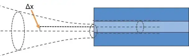
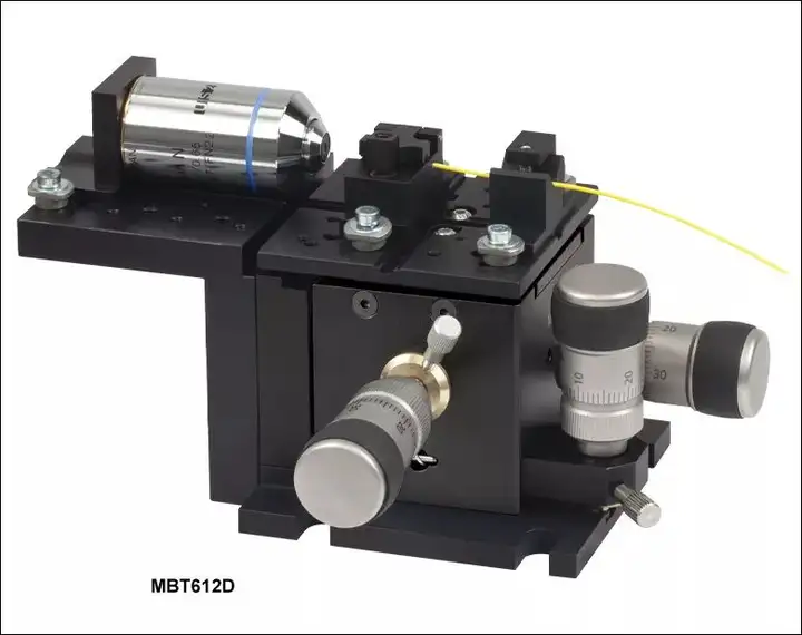
The lateral or angular deviation between the incident beam and the fiber core will significantly reduce the coupling efficiency, so fiber coupling requires high-precision motion control and positioning. For example, a three-dimensional flexible displacement stage and a differential regulator are a good combination.
In order to focus the beam to the correct size, which is equal to the mode field diameter, the focal length can be determined based on the wavelength, fiber mode field diameter, and input collimated beam diameter (d) when selecting a coupling lens: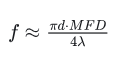
Take SMF-28 fiber coupling as an example. Suppose we need to couple a collimated Gaussian beam with a wavelength of 1550 nm and a diameter of 3 mm into an optical fiber. Then a 10.4 μm spot can be obtained through a lens with a focal length of 15.8 mm. If the actual focal lengths do not match exactly, a lens with a slightly smaller focal length is generally used. This gives a slightly smaller spot, with less impact on coupling efficiency. Therefore, we can choose a standard lens with a focal length of 15.5 mm.
![Singi Cable[Email: singi100@singi.com]](/u_file/2303/photo/11c1fa1eb8.jpg)

